Contents
To see the analogies more clearly, examine the following table that shows the
constitutive relationships for the various analogous quantities. The entries
for the mechanical analogs are formed by substituting the analogous quantities into
the equations for the electrical elements. For example the electrical version
of Ohm's law is e=iR. The Mechanical I analog stipulates that e is replaced
by v, i by f and R by 1/B, which yields v=f/B.
Since the energy of the mass in a Mechanical 1 analogy is measured relative to
mechanical "ground" (i.e., velocity=v=0) the energy of the capacitance must
be measured relative to electrical ground (i.e., voltage=e=0).
To apply this analogy, every node in the electrical circuit becomes a point in the mechanical system. Ground becomes a fixed location, resistor become friction elements, capacitors become masses and inductors become springs. Sources must also be transformed. A current source becomes a force generator, and a voltage source becomes an input velocity. This is best illustrated with an example.
Another way to do the switch from electrical to mechanical 1, is by simply redrawing the electrical circuit using mechanical components.
This diagram is that same diagram as that obtained previously, so we know it is correct.
This circuit was drawn with the capacitor grounded. If the capacitor is grounded the position of the mass can be chosen as an absolute position (relative to the fixed reference). If the capacitor is not grounded we must use relative positions and the result is much more complicated.
Proof that above analog
is correct.
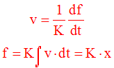
One deficiency in this analogy is that it only works easily for inductors with
only one current defined through them. This can be seen by the analogies between
energy in an inductor and energy in a mass.
Since the energy of the mass in a Mechanical 2 analogy is measured relative to
a fixed reference (i.e., a single velocity=v=0) the energy of the inductance must
be measured relative to a single current.
To apply this analogy, every loop in the electrical circuit becomes a point in the mechanical system. Resistors become friction elements, capacitors become springs and inductors become masses. Sources must also be transformed. A current source becomes an input velocity, and a voltage source becomes a force generator. This is best illustrated with an example.
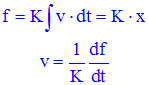
The reason for choosing the currents so that only one current flows through the
inductor now becomes apparent -- if chosen in this way, the position of the mass
can be chosen as an absolute position (relative to the fixed reference). It
needn't be done this way but, if not, the result is
much more complex.
In general, to draw a mechanical 2 analog of an electrical circuit, simply sum voltages around each loop, and equate these to the forces being applied at a point. If possible, draw currents such that only one current flow through inductors (so that the velocity of the mass can be defined in absolute terms relative to a fixed reference).
A visual method can be done, but will not be discussed here. It is similar to the method for drawing dual circuits (i.e., mechanical elements are drawn perpendicular to the electrical elements so the each loop in the electrical circuit becomes a position in the mechanical circuit).
http://lpsa.swarthmore.edu/Analogs/ElectricalMechanicalAnalogs.html
Background
It is possible to make electrical and mechanical systems
using analogs. An analogous electrical and mechanical system will have
differential equations of the same form. There are two analogs that are used
to go between electrical and mechanical systems. The anal
ogous quantities
are given below.Key Concept: Analogous Quantities
| Electrical Quantity |
Mechanical Analog I (Force-Current) |
Mechanical Analog II (Force Voltage) |
|---|---|---|
| Voltage, e | Velocity, v | Force, f |
| Current, i | Force, f | Velocity, v |
| Resistance, R | Lubricity, 1/B (Inverse friction) |
Friction, B |
| Capacitance, C | Mass, M | Compliance, 1/K (Inverse spring constant) |
| Inductance, L | Compliance, 1/K (Inverse spring constant) |
Mass, M |
| Transformer, N1:N2 | Lever, L1:L2 | Lever, L1:L2 |
Key Concept: Analogous Equations
| Electrical Equation |
Mechanical Analog I (Force-Current) |
Mechanical Analog II (Force Voltage) |
|---|---|---|
 |
 |
 |
 |
 |
 |
 |
 |
 |
 |
 |
 |
 |
 |
 |
 |
 |
 |
 |
 |
 |
 |
 |
 |
 |
 |
 |
| voltage of ground=0 (you can apply any current to ground and voltage remains 0) |
velocity of ground=0 (you can apply any force to ground and velocity remains 0) |
??? |
Converting Between Systems
Electrical to Mechanical 1 (Force-Current).
The important relationship when converting from a circuit to the Mechanical 1 analog is that between Kirchoff's Current Law and D'Alemberts Law (with inertial forces included).| Electrical | Mechanical 1 |
|---|---|
|
|
|
One deficiency in this analogy is that it only works easily
for capacitors that are grounded. This can be seen by the analogies between
energy in a capacitor and energy in a mass, and the analogy between electrical ground
(unchangeable voltage=0) and mechanical "ground" (immoveable position).
| Electrical | Mechanical 1 |
|---|---|
|
|
|
| voltage of ground=0 (you can apply any current to ground and voltage remains 0) |
velocity of ground=0 (you can apply any force to ground and voltage remains 0) |
To apply this analogy, every node in the electrical circuit becomes a point in the mechanical system. Ground becomes a fixed location, resistor become friction elements, capacitors become masses and inductors become springs. Sources must also be transformed. A current source becomes a force generator, and a voltage source becomes an input velocity. This is best illustrated with an example.
Procedure for Conversion from Electrical to Mechanical 1
The conversion from an electrical circuit to a mechanical 1 analog is easily accomplished if capacitors in the circuit are grounded. If they are not, the process results in a mechanical system where positions must be chosen very carefully, and the process can be much more difficult.Example: Conversion from Electrical to Mechanical 1 -- Mathematical Method
| Start with an electrical circuit. Label all node voltages. |
 |
| Write a node equations for each node voltage |
   |
| Re-write the equations using analogs (make making substitutions from the table of analogous quantities), with each electrical node being replaced by a position. |
  |
| Draw the mechanical system that corresponds with the equations. |
 |
Another way to do the switch from electrical to mechanical 1, is by simply redrawing the electrical circuit using mechanical components.
Example: Conversion from Electrical to Mechanical 1 -- Visual Method
| Start with an electrical circuit. Label all node voltages. |
a |
| Draw over circuit, replacing electrical elements with their analogs; current sources replaced by force generators, voltage sources by input velocities, resistors with friction elements, inductors with springs, and capacitors (which must be grounded) by masses. Each node becomes a position (or velocity) |
 |
| Label currents, positions, and mechanical elements as they were in the original electrical circuits. |
|
This diagram is that same diagram as that obtained previously, so we know it is correct.
This circuit was drawn with the capacitor grounded. If the capacitor is grounded the position of the mass can be chosen as an absolute position (relative to the fixed reference). If the capacitor is not grounded we must use relative positions and the result is much more complicated.
Mechanical 1 (Force-Current) to Electrical.
The procedure to go from Mechanical 1 to Electrical is simply the reverse of Electrical to Mechanical 1. Either a mathematical method can be used (refer to previous example, Electrical to Mechanical 1, and read the table from bottom to top, or a simple visual method can be used where force generators are replaced by current sources, friction elements by resistors, springs by inductors, and masses by capacitors (which are grounded). Each position becomes a node in the circuit.Example: Conversion from Mechanical 1 to Electrical -- Visual Method
| Start with the mechanical system. Label all positions. |
 |
| Draw over circuit, replacing mechanical elements with their analogs; force generators by current sources, input velocities by voltage sources, friction elements by resistors, springs by inductors, and masses by capacitors (which are grounded). Each position becomes a node. |
 |
| Label nodes and electrical elements as they were in the original mechanical system. |
 |
Key Concept: Simple method to go between Electrical and Mechanical 1
Draw over circuit (or over mechanical system). Swap:- current sources↔force generators;
- voltage sources↔input velocities;
- resistors↔friction elements;
- inductors↔springs;
- capacitors (which must be grounded)↔masses;
- and ground↔fixed reference.
Electrical to Mechanical 2 (Force-Voltage).
The important relationship when converting from a circuit to the Mechanical 2 analog is that between Kirchoff's Voltage Law and D'Alemberts Law (with inertial forces included).| Electrical | Mechanical 2 |
|---|---|
|
|
| Electrical | Mechanical 2 |
|---|---|
|
|
To apply this analogy, every loop in the electrical circuit becomes a point in the mechanical system. Resistors become friction elements, capacitors become springs and inductors become masses. Sources must also be transformed. A current source becomes an input velocity, and a voltage source becomes a force generator. This is best illustrated with an example.
Procedure for Conversion from Electrical to Mechanical 2
Converting a circuit diagram to a mechanical 2 analog uses a similar procedure as electrical to mechanical 1 except that the voltages around a loop summed to zero (instead of the sum of currents at a node) is analogous to the sum of forces at a point being summed to zero .Example: Conversion from Electrical to Mechanical 2 -- Mathematical Method
| Start with an electrical circuit. Label all currents. Choose currents so that only one current flows through inductors. |  |
| Write a loop equations for each loop. |  |
| Re-write the equations using analogs (make making substitutions from the table of analogous quantities), with each electrical loop being replaced by a position. |
 |
| Draw the mechanical system that corresponds with the equations. |
 |
In general, to draw a mechanical 2 analog of an electrical circuit, simply sum voltages around each loop, and equate these to the forces being applied at a point. If possible, draw currents such that only one current flow through inductors (so that the velocity of the mass can be defined in absolute terms relative to a fixed reference).
A visual method can be done, but will not be discussed here. It is similar to the method for drawing dual circuits (i.e., mechanical elements are drawn perpendicular to the electrical elements so the each loop in the electrical circuit becomes a position in the mechanical circuit).
Mechanical 2 (Force-Voltage) to Electrical.
The procedure to go from Mechanical 2 to Electrical is simply the reverse of Electrical to Mechanical 1. Refer to the previous example, Electrical to Mechanical 2, and read the table from bottom to top. A visual method can be done, but will not be discussed here.http://lpsa.swarthmore.edu/Analogs/ElectricalMechanicalAnalogs.html
No comments:
Post a Comment